
Operation mode
Functional principle
The fields of application for the horizontal peeler centrifuge are as well in the chemical and pharmaceutical as in the starch and basic industry. The multi-purpose possible application of our centrifugal system implicates, that no general batch cycle can be described. Rather the user has to define the optimal process by means of his product and process experiences. Of course we are quite willing to support with our experiences. Subsequently a batch cycle, exemplary for the processing of wheat starch, will be described. Therefore it has no universal validity. 
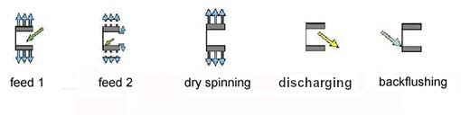
The individual process steps are filling process I and II, dry spinning at an increased rotation speed and discharging of the rotor at an again reduced rotation speed. These process steps are followed by the backflushing process for regenerating of the sandwich filtration element in a fixed rhythm after several batches. However, the rotation speed and the time required for the individual process steps cannot be freely measured, but were instead assessed in preliminary tests with a lot of sensitivity with the background of many years experience in the centrifugal dewatering of wheat starch on the basis of plausibility considerations. By optimizing the individual steps, starch with an excellent low-protein quality will be produced now.
Filling I
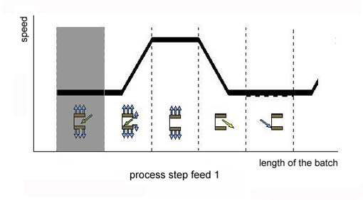
Step 1: Filling I in sequence of the processing steps
The benchmark for the operation of the centrifuge is the predominant demand to operate it in such a way, that by a high throughput the residual moisture of the starch cake and the protein content that remains in the starch are reduced to a minimum. Should this happen, the protein may not enter the deeper layers of the forming cake in view of the small differences in the densities of starch milk and protein as well as the almost equal grain sizes, too. Moreover, the protein may not have time to accumulate in the solid cake. For that reason, the efforts results on the one hand in feeding a large quantity of starch milk into the rotor on the other hand operating with the lowest conceivable speed. It’s the aim to keep the filtration power such at a very low level that a filter cake front can build oneself up. As the protein particles sink lower than the starch particles due to the lower density of the protein, most of the protein swims on the surface. The starch cake formed below however remains largely protein-free. In order to ensure an even distribution of the suspension across the entire length of the rotor, and therefore above all to counteract the formation of protein clusters in the area of the rotor wall and the edge ring, the initial filling process, meaning filling I, has to be carried out in any case concentrically. Herby no interfered unbalances will be generated by an optimal operation of the combined function unit and the backflushing rotor. The filling quantity has to be calculated in such a way that within the filling time I the starch cake and the suspension rise up just before the edge ring. The typical times for filling (filling I) are between 4 and 15 seconds depending on the rotor size and the starch quality.
Filling II
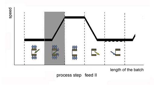
Step 2: Filling II in sequence of the processing steps
The task of the filling process in phase filling II is to flush out the floating protein across the edge ring. Therefore, the flow rate during filling process II must be adjusted in such a way that the starch is just able to sediment and the protein can float. In order to prevent in any way the sedimentation of the floating protein at the beginning of filling phase II, filling II still starts before to the end of filling phase I. That means both processes overlap temporally. Otherwise, a part of the protein would sediment directly when the filling flow is interrupted. This would result in a brownish-yellowish interim layer in the cake. Then a further filtration would be impossible. Prerequisite for this method is that the starch milk is now fed at the bottom of the rotor, meaning in the rearmost rotor area, so that the flow, directed towards the edge ring, can flush out the floating protein across the entire length of the rotor. As the starch milk fed at the rear part of the rotor sediments partially forthwith due to the centrifugal force, a cone-shaped starch cake will be formed during the second filling step, which lasts considerably longer. The starch milk then flows down this cone.
Another characteristic of filling step II is that the filtration performance no longer substantially depends on the number of revolutions due to the increased porosity of the filter cake. The rotation speed also no longer has a direct influence on the intensity of the starch milk / protein separation. Hereby it is already possible to accelerate the rotor to a high dry spinning speed during the last phase of filling process II. As a consequence, the otherwise required down time for a subsequent acceleration can be saved and altogether shorten the batch. The second filling process can be considered as finished as soon as the cake starch has reached the edge ring. In order to flush out any remaining impurities of the surface, it is recommended to extend the filling process II at about 10 to 15 seconds above the absolutely required filling time.
Due to the low speed in filling phase I and in the initial phase of filling phase II, the starch cake remains porous and thus capable for filtration. In spite of the relative low g-force factor, most parts of the liquid will be still filtered out of the starch cake so that additional liquid can only be extracted from the cake by increasing substantially the g-force factor during the following dry spinning step.
The decisive creative basis for a sustained protein extraction with an altogether automatic operation, however, is the turning of the design from the sieve basket to the backflushing rotor. While using sieve baskets in combination with turbo couplings, that means with almost constant rotation speeds, the separation of solids is based on the filtration principle, the separation in backflushing rotors will be effected by a combination of sedimentation and filtration. This difference in the dehumidification process enables the use of completely different filter cloths. While the filtration performance at the dehumidification with sieve basket has to be kept low at the beginning of the batch due to the protein separation, it is merely sufficient for a separation according to the sedimentation principle to adjust the filter cloth in an optimal way to the dewatering process. An initially high filtration resistance is therefore not only required when using backflushing rotors, but actually impairs the process as a matter of fact. As a consequence, the embedding of protein in the filter level (heel cake) is not given when using the backflushing rotor. The regeneration takes place through the periodic feed of a backflushing liquid.
At classic sieve basket, the heel cake has to be removed in 8-hour intervals by hand. Other designs require the daily exchange of the filter cloth. This elimination of the manual intervention using the backflushing principle ultimately enables its process automation.
Another important design prerequisite for an optimal rotor filling is the functionally geometric arrangement and design of the filling components as well as the correct fluidic dimensioning of the geodetic height of the supply container respectively the pump capacity. Otherwise in case of a poor design of these components, there is the risk that the flow resistance inside the feed components increases in such way that the starch milk sediments immediately in the backflushing rotor due to the delayed feed and consequently the starch cake gets contaminated with protein.
Dry Spinning
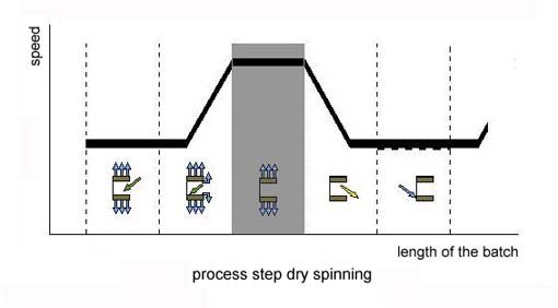
Step 3: Spinning in sequence of the processing steps
Shortly before the end of filling phase II, the backflushing rotor accelerates to spinning speed as already explained. As the filter cake will retained its high filtration capacity during filling phase I due to the operational process described beforehand, the filtrate volume removed out of the cake again strongly increases with increasing of the centrifugal pressure. This results in a permanent residual humidity of around 33% – 35% for wheat starch under production conditions.
The decisive advantage of this increased dehumidification is the reduced final thermal drying. According to the bond diagram, a still more intensive dehumidification would only be possible with an additionally increasing of the g-force factor. However, with regard to the stability of the rotor, especially at sieve baskets, the increase of this factor is at present commercial not possible. On the other hand the time factor does not have an effect on the attainable degree of dehumidification. Therefore, longer dehumidification times do not improve the result in any way. The centrifugation process is terminated when the equilibrium condition during the saturation process is achieved.
In this context, it has to be point out, too that the starch enters a sticky consistency with a slightly higher humidity. Consequently, the resistance, which the starch subtends in further processing, also increases strongly. For this reason, too, a permanent and steady high dewatering is very advantageously with regard to an trouble-free production process.
Discharging
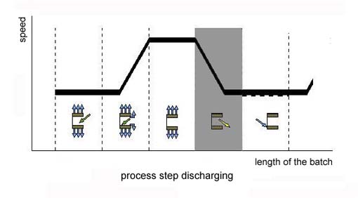
Step 4: process step discharging
The dewatered starch will be discharged in the final process step. The discharging process already starts at the beginning of deceleration, meaning at full dry spinning speed.
For that purpose, the peeling knife of the combined function unit, which is aligned parallel to the rotation axis, will be swivelled into the starch cake electro-mechanical. Due to the cone shape of the cake surface, only a part of the starch cake is initially removed and hence the peeler only moderately strained. Although the cake layer covered by the peeler increase when the combined function unit continues to swivel in, the rotation speed decreases substantially at the same time. Right before the end of the discharging process, the rotation speed is down to the filling speed. Then the discharging process only continues for another 10 to 20 seconds at the same speed while the combined function unit continues to swivel in. The residual layer has height of approx. 2 – 5 mm.
Backflushing
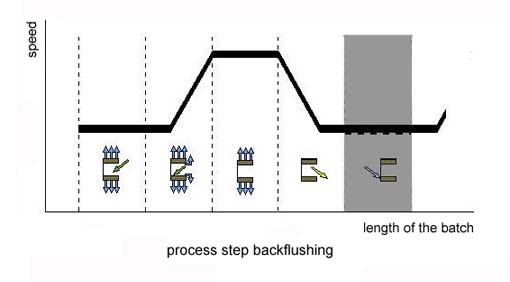
Step 5: Backflushing in sequence of the processing
In spite of the minimized residual layer, this has to be backflushed in batch intervals which depend on the product and especially on its protein content. Two reasons are decisive for this purpose: on the one hand, protein particles initially sediment on the remaining residual layer with each new filling, and cover the latter with a wax-like layer, which interfere the filtration process in the long run respectively, stops it entirely. Additionally, the residual layer inadmissibly compacts with the reiterated discharging processes. Both together effects, that the cake becomes impermeable. With backflushing, the residual layer will be softened and suspended into the filter cake formed in the filling process which follows backflushing. For that purpose, liquid is fed into the backflushing chamber via the backflushing pipe. At the same time, the filtrate peeler pivots out of the backflushing chamber so that the liquid that is fed to the chamber rises to the level of the remaining residual layer. The washing liquid now enters the drainage channels of the slotted bridge screen according to the principle of communicating tubes, penetrates the sandwich filter element subsequently and in the end the residual layer deposited on it. As a result, the residual layer largely dissolves in the following batch into the again feeding starch milk.